Case Study: High-Speed Cameras Aid Wing Deformation Measurement Test in Wind Tunnels
In this wind tunnel testing application, German-Dutch Wind Tunnels chose Emergent 10GigE cameras with 20MP CMOS sensors because its optical fiber interface allowed them to run all four cameras from the wind tunnel simulation to a single remote PC.
German-Dutch Wind Tunnels (DNW) is one of the leading wind tunnel service providers in the world and was set up by the German Aerospace Center (DLR) and the Royal Netherlands Aerospace Centre (NLR). DNW operates six wind tunnels in Germany and the Netherlands, including in Brunswick, Göttingen, Amsterdam, and DNW’s headquarters in Marknesse. By placing aircraft, vehicle, building, or other solid models in an airstream of known velocity, wind tunnels allow researchers to investigate airflow around objects or the effect of wind on objects. DNW operates one of Europe’s largest wind tunnels and provides experimental simulation solutions for aerodynamic research and development projects from academia and the aeronautical industry, as well as from automotive, civil engineering, shipbuilding, sports, and other industries.
DNW provides experimental aerodynamic simulations. By running six wind tunnels, including subsonic, transonic, and supersonic facilities, DNW can evaluate almost all airflow characteristics found in engineering and nature. DNW supplies data to industry from aerodynamic, aero-acoustic, and aero-elastic simulation techniques by testing (scaled) models in a controlled environment. It offers a wide range of simulations. Typical applications include performance characterization of takeoff, landing, and cruising aircraft configurations; aero-acoustic investigations for airframe noise reduction; and simulation of aircraft propulsion in both isolated and installed configurations.
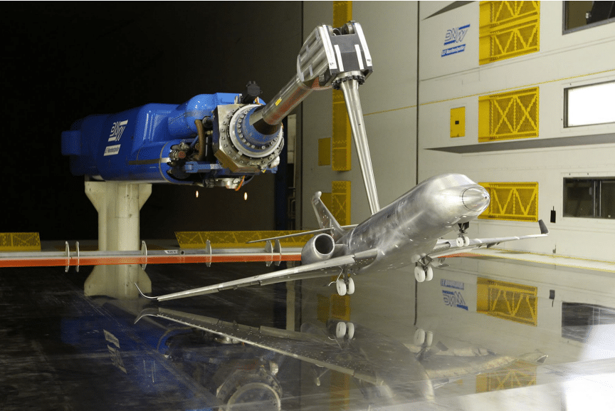
Wind tunnel tests are typically highly specialized and challenging (Figure 1). Wind tunnel models are complex and instruments are high tech. In addition to extremely tight manufacturing tolerances and meticulous surface finishing, models are equipped with a large amount of measurement equipment and control systems, such as force balances, air motors, and remote controls. In addition, aerodynamic and aero-acoustic simulations often require sophisticated engineering. For instance, for in-ground effect, the ground below the object under test is simulated with an integrated moving belt system. The moving belt, also known as a rolling road system, is a 7.92 x 9.6 m steel belt integrated into the wind tunnel floor. It moves synchronously with the air up to wind speeds of 80 meters per second. Integrating all simulation, control, and measurement technologies into a productive, cost-effective wind tunnel test is a daunting task. Highly trained DNW staff work closely with customers and suppliers to prepare projects in detail and to work toward innovative solutions for future sustainable aviation.

Figure 1: A model of a Dassault Falcon business jet in close proximity to the moving ground plane in the DNW-LLF wind tunnel (image courtesy of Dassault Aviation).
Stereoscopic Point Tracking System
A key capability for DNW is extracting as much high-quality data from a wind tunnel test as possible. To increase the quality and cost-effectiveness of its services, DNW is continuously developing high-level expertise in measurement techniques and analysis of test results. DNW routinely employs techniques for measuring surface pressures, forces, velocity, and noise. Evaluating aircraft performance involves a precise knowledge of exact propeller, rotor blade, and wing geometry. Under the various wind loads that occur from takeoff through landing, wind tunnel model parts deform, resulting in wing bending and twisting. A stereoscopic point tracking system developed by DNW measures such model deformation by simultaneously tracking markers from different angles during wind tunnel tests.
The system is flexible enough to facilitate a variety of experimental simulations, handling virtually any marker quantity, distribution, and layout. One current application is an EU-funded project called UHURA (funded under EU Horizon 2020 Grant Agreement no. 769088). The UHURA projects aims to develop numerical tools for unsteady high-lift aerodynamics. The Krueger flap, a leading-edge device, promises to enable laminar wing technology. This technology is seen as the major single source for drag reduction on the airframe of a transport aircraft and will be a key technology in achieving targets for emissions reduction. The Krueger flap could perform a dual function by both increasing aerodynamic high-lift performance and shielding the leading edge from contamination during takeoff and landing. Due to its specific deployment path, engineers need good knowledge of the flow during transient behavior and exact part position and geometry.
Experimental measurements from DNW wind tunnels give UHURA a unique dataset for validation of advanced computational fluid dynamics (CFD) models. With detailed flow measurements from particle image velocimetry (PIV) and model deformation measurements, interactions between the fluid and the wing structure can be investigated. The resulting understanding feeds into techniques for predicting behavior and design optimization of high-lift devices for transport aircraft systems. Such advanced methodologies enable more complex part designs and significant reductions in design lead times for aircraft manufacturers.
Long Camera Cable Runs Required
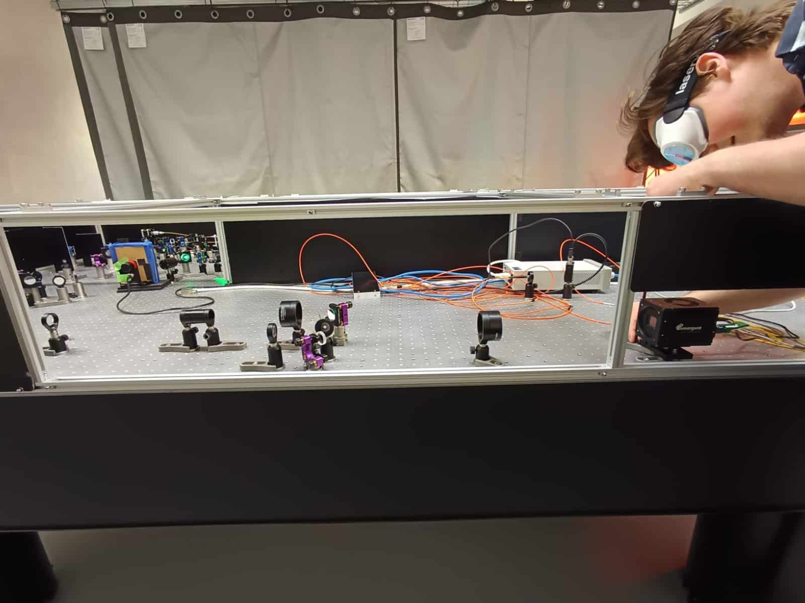
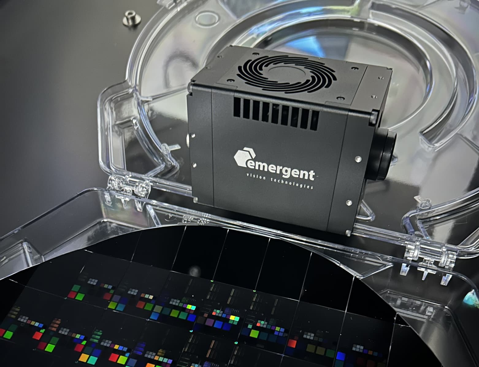
Depending on the type of test, DNW uses two or four 20 MP, 10GigE HR-20000 cameras from Emergent Vision Technologies (Figure 2) to monitor wind tunnel models equipped with nonintrusive markers. HR-20000 cameras feature the 35 mm full-frame optical format CMV20000 CMOS sensor by AMS. At full 5120 × 3840 resolution, this camera achieves 32 fps. The HR-20000 also offers multi-camera synchronization at < 1µs and low CPU overhead. The stereo camera setup requires that four cameras be mounted some distance apart in wind tunnels so they can capture images of markers from different angles. According to Gerrit Feenstra, instrumentation engineer at DNW, the HR-20000 cameras were selected because of their excellent price/performance ratio and an optical fiber interface that allows cable runs up to 10 km without the need for fiber converters or repeaters.
“Before Emergent came out with their 10 Gigabit Ethernet optical fiber interface, we had complicated test setups. Cable length restrictions of 2 to 3 meters between camera and computer meant that the stereo imaging systems required using two PCs within the wind tunnel,” Feenstra explains. “Emergent’s optical interface is a much better fit because we can run all four cameras from the wind tunnel simulation to a single remote PC, which can be set up in a much more convenient location.”

Figure 2: DNW relies on HR-20000 cameras from Emergent Vision Technologies for precise positioning of models for aeronautical simulations and wind tunnel testing.
Deformation Measurements
Based on tracking the three-dimensional coordinates of markers applied to objects under test, the stereo point tracking measurement technique has been successfully applied in projects ranging from high-speed tracking of falling objects and passenger airplane wing deformation measurements to high-accuracy helicopter rotor tracking experiments. In these experiments, a marker grid array with known coordinates is applied to the object under test. Markers can be either actively controlled flush-mounted light sources or passive fluorescent adhesive or spray-painted markers.
During model deformation tests for the UHURA project, the Emergent camera setup captures video of passive fluorescent markers arranged on a model of the wing and Krueger device as they deploy and retract under various aerodynamic simulations in the wind tunnel (Figure 3). The high-precision three-dimensional marker locations obtained from custom image analysis software serve as input for calibration software, which correlates between the two-dimensional digital camera image planes and the model’s measurement volume.
Further image analysis determines geometric properties of the model, such as its precise attitude, position, and bending and twist distribution. Wing deformation is represented by modeling a 3D, finite element surface geometry (triangular wireframe in space without discontinuities) based on individual marker grid points. Data that include statistical error estimates based on error propagation algorithms are provided in real time (up to 500 Hz).
The spatial resolution of the system depends on camera type, lens system, model length scale, and marker configuration. Pixel resolutions are achievable to up to one-tenth of a pixel. Coordinate resolutions are dependent on camera chip size and model size (order of magnitude 1/(10 * R), where R is the amount of pixels per imaged meter). For a typical full-span wind tunnel model, coordinate detection accuracy is approximately 0.5 ‰ of the chord length for wing displacement and 0.1 degree for wing twist (torsion).

Figure 3: During model deformation tests for the UHURA project, the stereo camera setup in the wind tunnel captures video of passive fluorescent markers arranged on a model of a wing and Krueger flaps as they deploy and retract under various aerodynamic simulations.
UV Illumination Technique
During each experiment, after wind tunnel conditions are set, tunnel illumination is dimmed and custom, high-power 405 nm UV light sources are activated. To generate sufficient illumination and contrast for marker detection by the camera system, the dozen or more light sources strategically placed in the wind tunnel rely on an array of 28, 30 W 405 nm LEDs. UV lights illuminate the markers, which reflect yellow back to the camera. According to Feenstra, using an optical long-pass filter suppresses UV illumination while still transmitting fluorescent light from the markers. This creates a high-contrast real black-and-white image that facilitates marker localization by the computer and construction of the 3D point cloud.
“We’ve been using the Emergent cameras since 2016 for precise positioning of the model in the wind tunnel and for deformation measurement,” says Feenstra. “They are constants, always installed in the tunnel, and are always running for every test, continuously monitoring the positioning of the model and tracking the markers. Their function is particularly important during in-ground effect investigations for takeoff and landing scenarios, which is most of what we do at the DNW, because the model could be damaged if it ever contacted the rolling road system, which simulates a runway moving below the aircraft model at 80 meters per second.”
Future Designs
Based on the initial success of the project using the 20 MP 10GigE HR-20000 cameras, DNW upgraded its cameras and purchased two HZ-21000-G cameras from Emergent Vision Technologies for future use. Part of the award-winning Zenith series of 100GigE cameras, these 21 MP cameras achieve a frame rate of 542 fps through a QSFP28 100GigE interface.
Recognized as a 2022 Top Innovation by inVISION magazine, the HZ-21000-G features Gpixel’s GSPRINT4521 global shutter CMOS image sensor. With the new cameras, DNW can achieve significantly faster frame rates with the same benefits offered by the HR-20000 cameras, including multi-camera synchronization at < 1µs and low CPU overhead.
FOR FURTHER INFORMATION:
Emergent Vision Technologies’ High-Speed Cameras:
https://emergentvisiontec.com/area-scan-cameras/


